Cloth Simulation
Real-Time Physical Simulation of a Cloth in an Environment
Chetan Khanna
May 2023
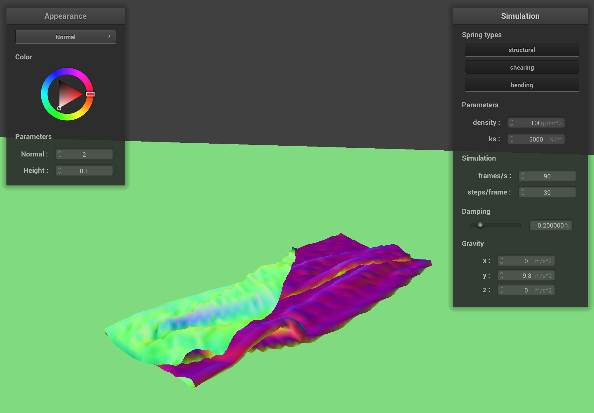

This project simulates the physics of a cloth based on a “mass-spring” philosophy. The cloth was represented by a mesh of vertices connected together by springs (of three types, each serving a different purpose: structural, shear, and bending). Simulating forces on these springs (and thus this grid) using physical laws (such as Hooke’s Law) realistically simulates the shapes and position of the entire cloth and visualize it.
I used Verlet integration was used to simulate the forces on these springs. In order to try and keep the simulation stable, Provot’s method to constrain the position of the springs at any time step was employed. This prevented the springs from “stretching out” just a little too far at some time step (which would eventually “balloon” as that addition force gets passed to the next spring) and the entire simulation “blowing up“.
I then implemented the ability for the cloth to intersect with spheres and planes in the scene. This enabled us to see how the cloth behaved when it collided with other objects.
After this, I also implemented the ability for the cloth to collide with itself. Since there was no checking for self collisions thus far, parts of the cloth could intersect and go through each other, which was physically unrealistic. In order to do this efficiently, I divided the cloth spatially into different “buckets” (based on a hash function I created) and put each vertex into a “bucket” (entry of our hashmap), and then for every point checked for collisions against the other points in that “bucket”. I then corrected points that were colliding. This improved the physical realism of the cloth—for example, enabling the cloth to fold on top of itself realistically when it collided with a plane.
The last part of the project was implementing shaders that allowed us to color the cloth in different ways. I implemented Blinn-Phong shading and Texture Mapping. I also implemented Bump and then Displacement Mapping, which used height maps to modify the normals and thus make the surface look bumpy. Displacement mapping went a step further: it made the surface actually be bumpy based on the height map by modifying the positions of the vertices. Our final use of the shaders was for environment-mapped reflections, allowing the cloth and sphere to effectively "mirror" the environment around us.
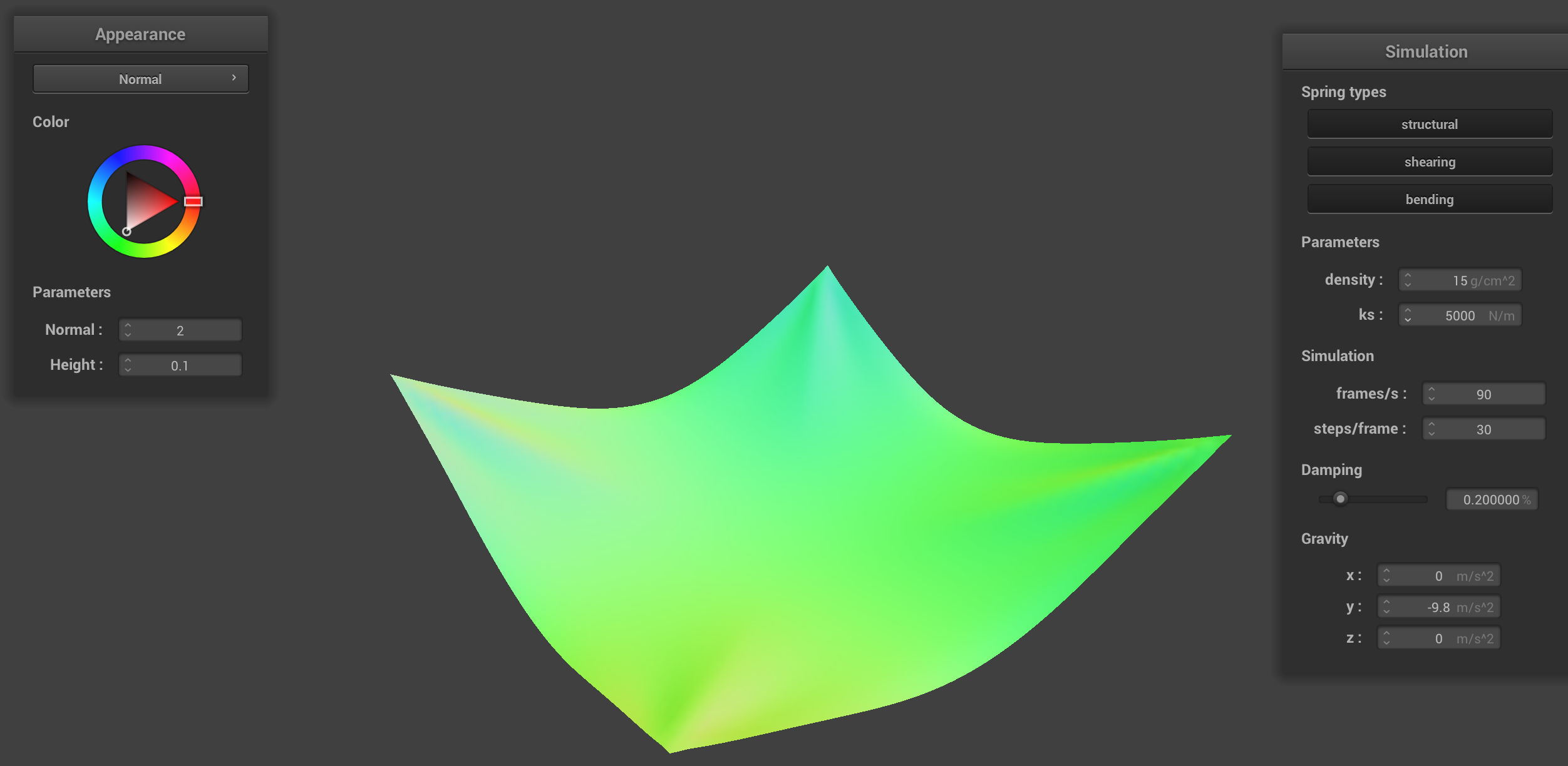
Experimenting with different constants
This section shows some results from this project. These results demonstrate the physically accurate nature of the simulation.
Reference view (default parameters)
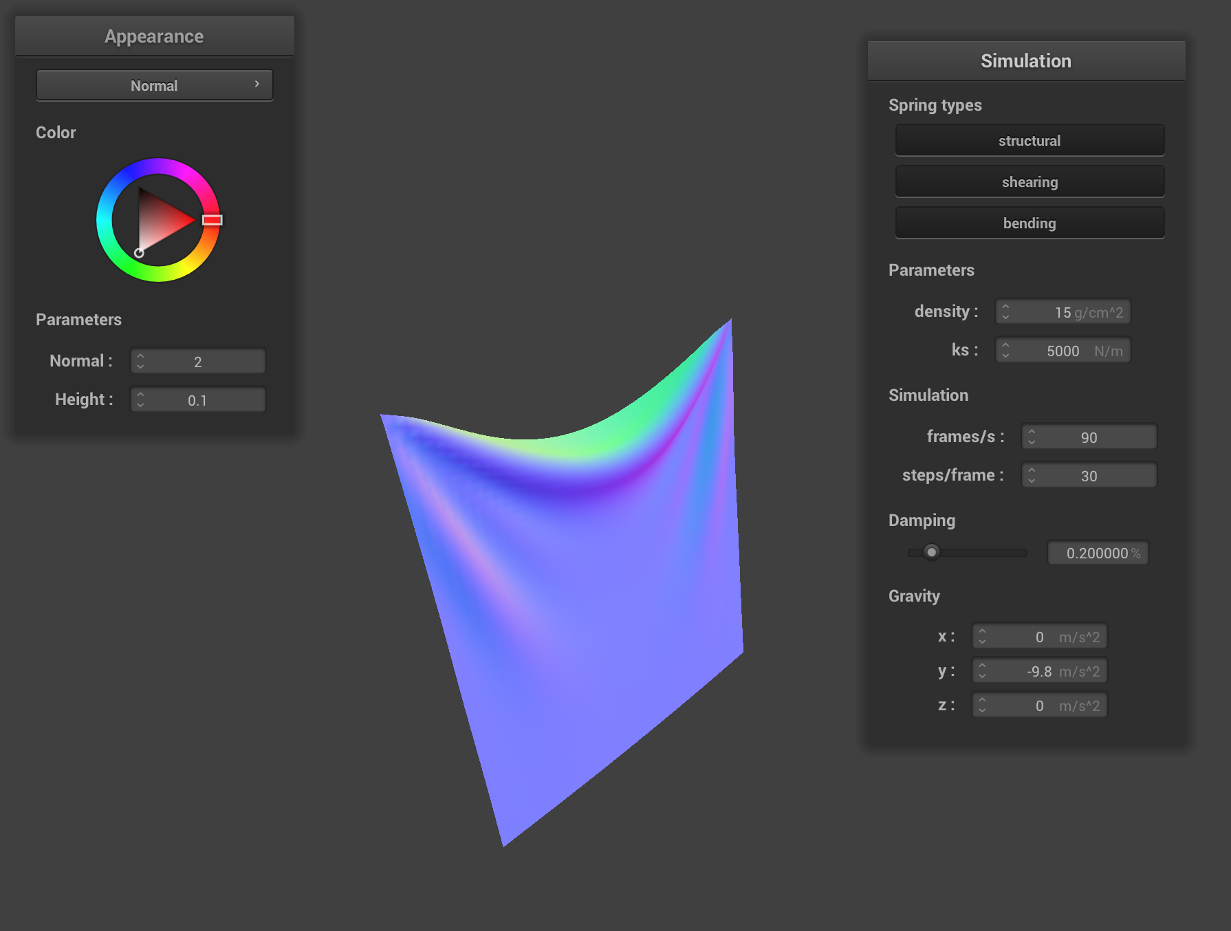
This is what the cloth looks like with default parameters ks = 5000, damping set to 0.2% and density = 15.
Changing the spring constant ks
Increasing spring constant: ks = 50000
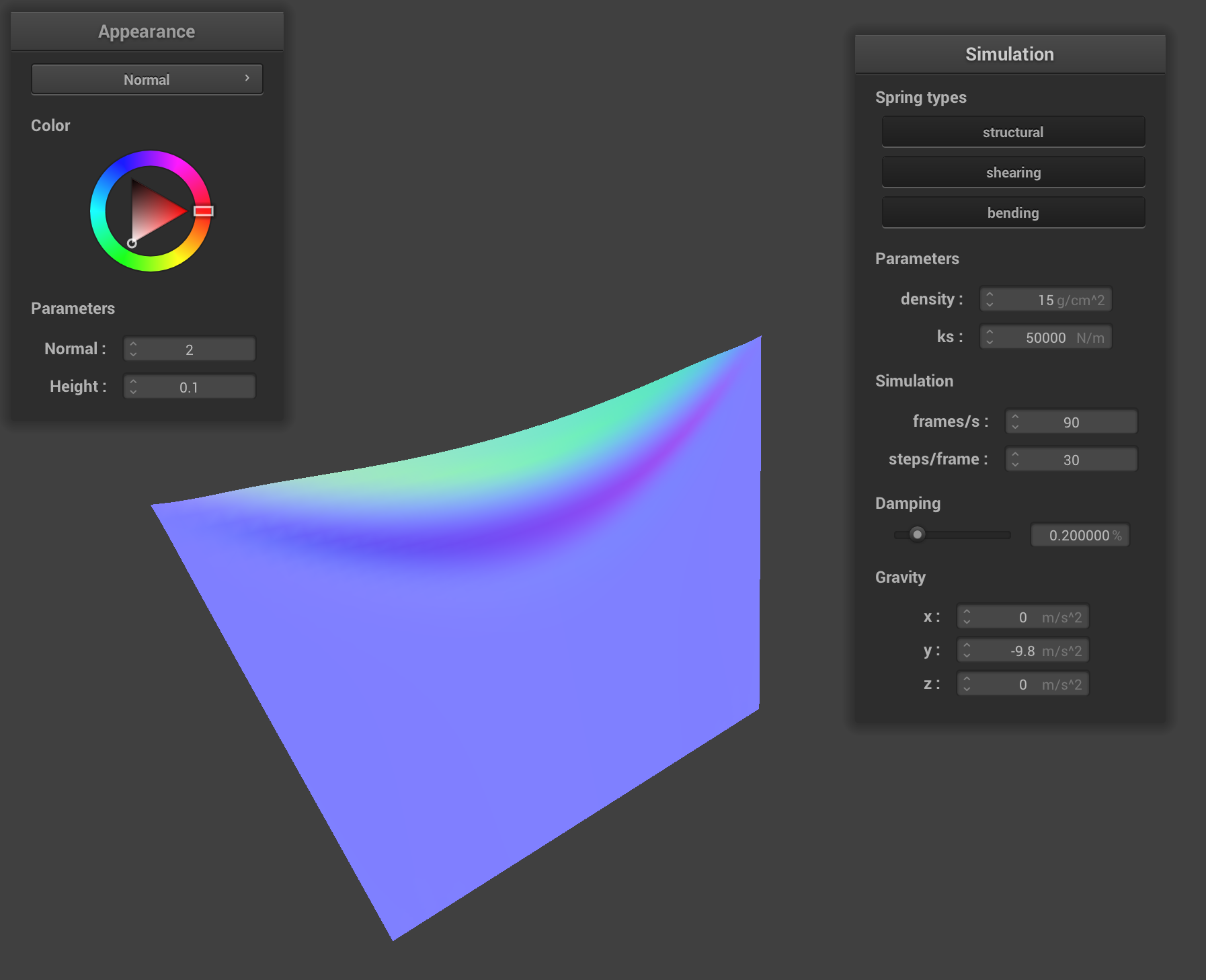
Increasing the spring constant from 5000 to 50000 did not appear to affect the speed at which the cloth “fell down” (at least significantly). However, the crease (at the upper part of the cloth) between the two pinned corners did become less prominent, and there are fewer creases (the cloth is straighter).
This is expected behavior; the springs require more force for any displacement, so the force of gravity is not causing as much of a displacement on the springs (or, perhaps more accurately, the force exerted by the lower strings on the upper ones isn’t affecting the displacement of the upper ones as much), thus causing the cloth to be less “stretchy” in a sense.
Decreasing spring constant: ks = 50
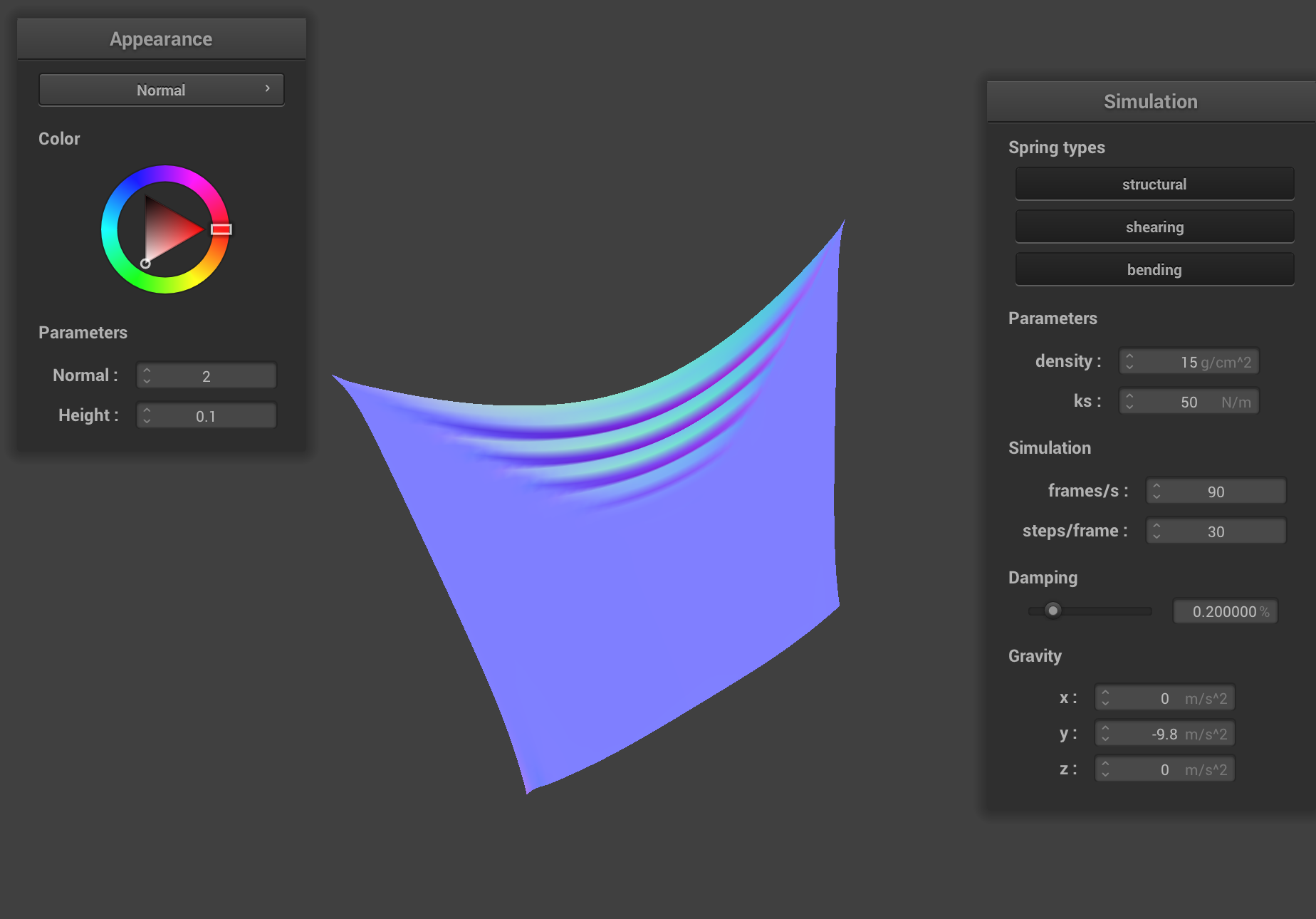
As expected, lowering the spring constant causes the cloth to be “stretchier”. There are multiple creases at the top now, rather than just one (and the dip between the two pinned corners is steeper). The cloth retains less of its shape, as can be demonstrated by the corners of the spring being very stretched out. This makes sense; it is the opposite of the case above, and thus even the “small” force applied by gravity affects the displacement of the springs more—and by one spring on the other).
Changing density
Increasing density: density = 1500
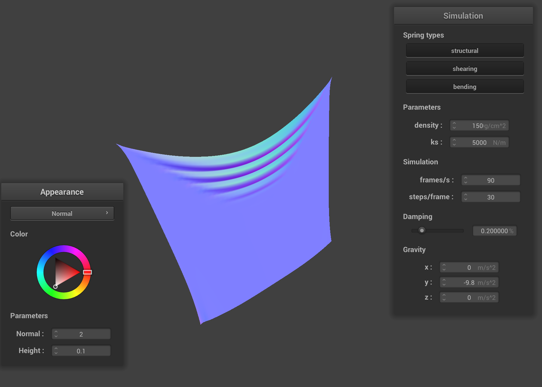
Increasing the density will increase the mass of the cloth.
Note how the increased density causes the cloth to drop more noticeably between the two pinned corners. This makes sense: a cloth density will mean the lower springs are pulling the upper springs down with more force (due to their larger mass).
(While the upper springs themselves may also have more mass, this doesn't outweigh the extra force of the lower springs—by the time we're at the top of the cloth, there are obviously many more springs pulling down on the cloth than pulling up on the cloth. “At the limit”, in other words, the mass of the upper spring would be virtually negligible compared to the mass of all the lower springs.)
For the same reasons, it also causes the cloth to appear “stretchier”. As expected (and for the opposite reason), the cloth will appear a lot less stretchy.
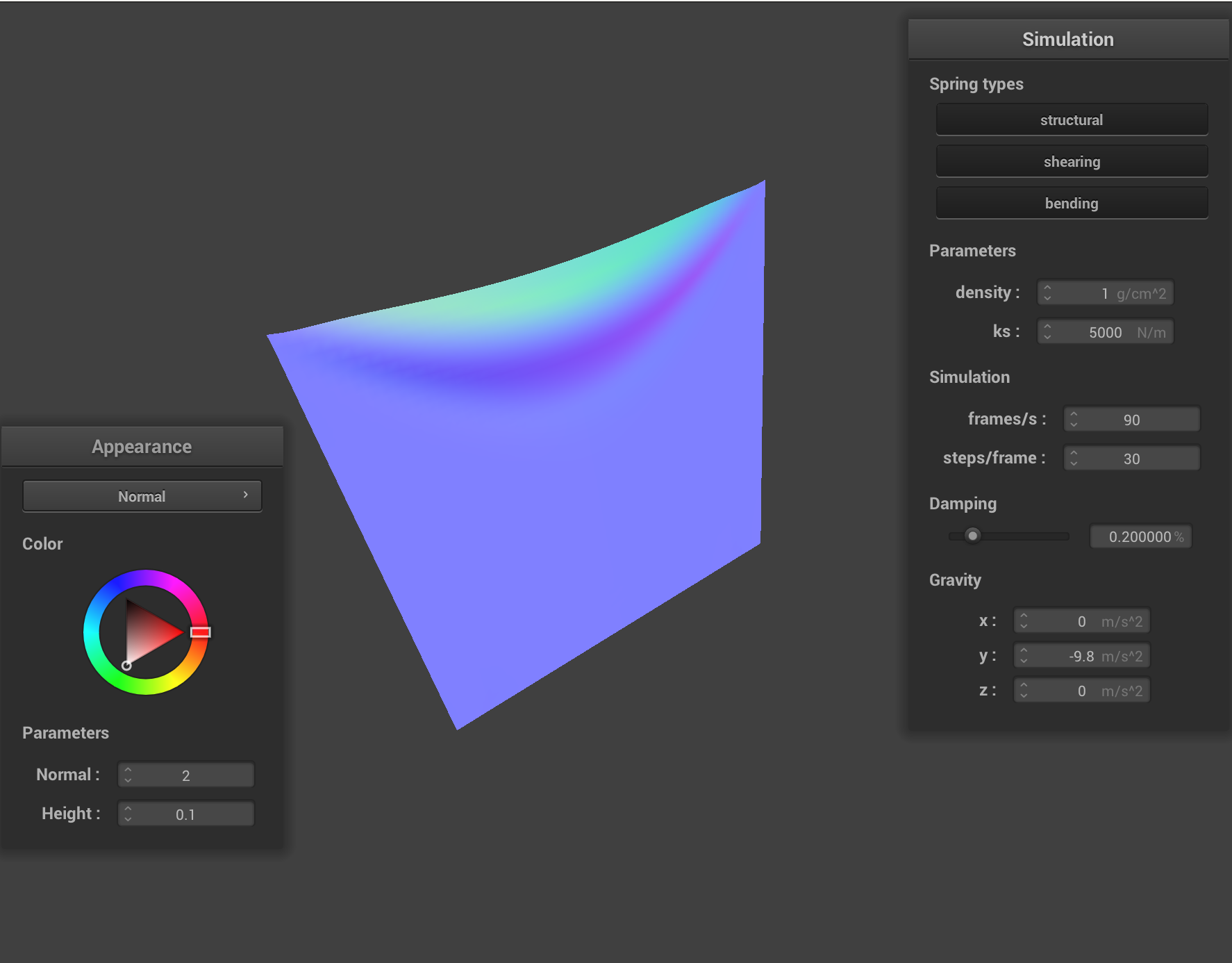
Impact of damping
A higher damping setting will slow down motion. During Verlet intgration, we multiply with (the velocity of the particle at time ) when updating a particle's position for the new timestep; in other words, we scale down a particle's velocity at every timestep.
Damping drastically changes how quickly the cloth falls down, and all it’s movement (e.g. even the movement of the cloth’s springs between themselves).
Most noticeably, it also affects how much the cloth “oscillates” once it falls down. At lower damping settings, the cloth falls but then continues to oscillate at high amplitude and frequency. This makes sense; a lower damping setting means that the cloth doesn’t lose as much energy, and thus by the time it reaches the bottom it has far too much excess energy. It continues to oscillate for a long time, only losing a very minor amount of energy each time.
Because damping (obviously) also applies to the cloth’s springs, we also note how the cloth appears a lot less “smooth”. This is because the spring’s are moving much more “violently” when a force is applied on them (and this effect compounds and travels through springs—hence the continued “instability” that lasts for long). A higher damping settings tends to “smooth” out this effect by making the slight force one spring applies on the other at one moment in time not impact the spring’s next position as much.
Naturally, a high damping setting has the opposite effect, and all motion is slowed down. The cloth falls down very slowly, and barely oscillates around the bottom before coming to rest.
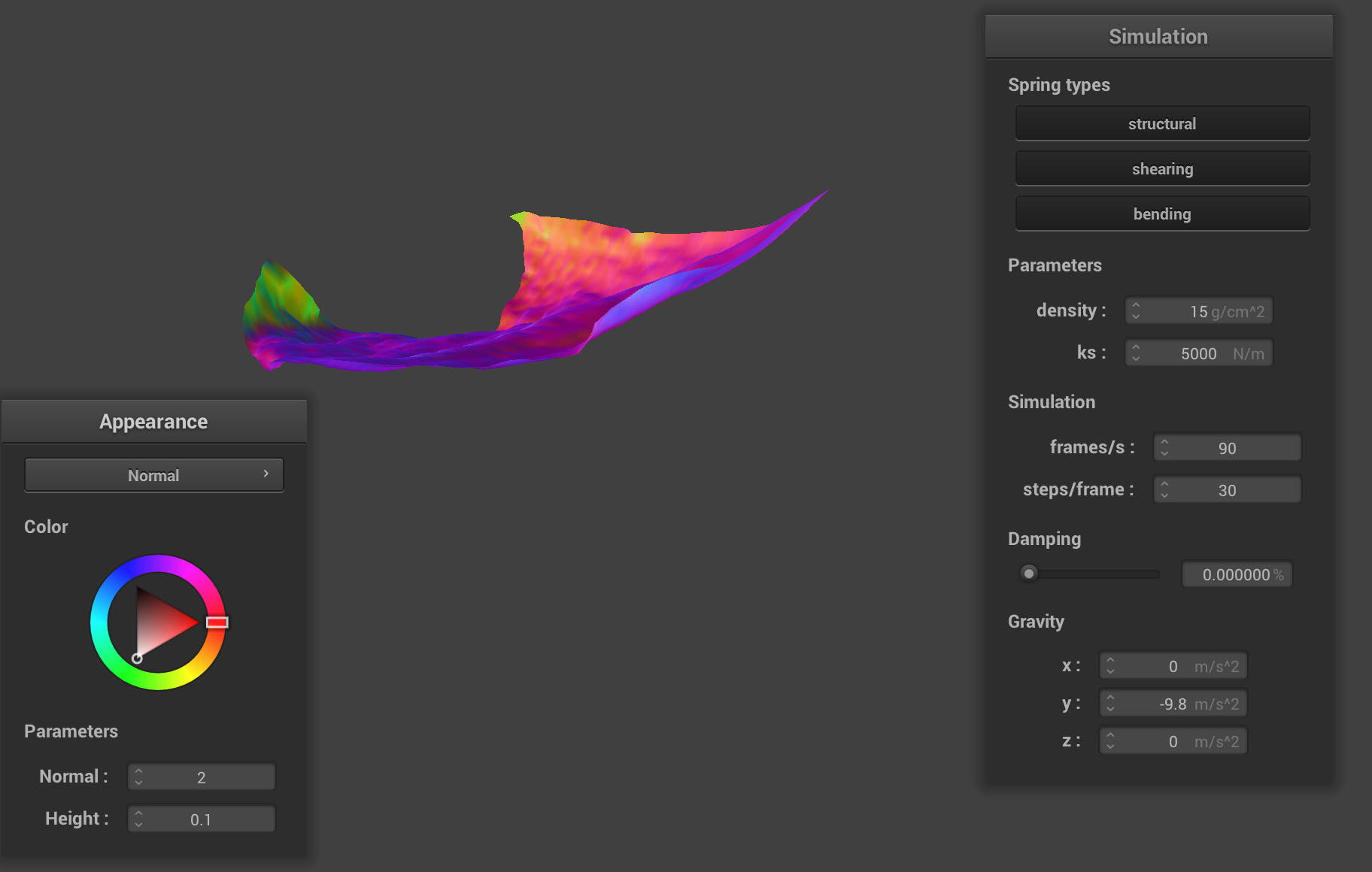
Illustration of the lack of damping: when the cloth first falls, it has so much energy that it is oscillating. Here the cloth is nearly 90 degrees offset from it’s rest point. Also note how the normals are often pointing in very different directions; a slight force applied by one spring on the cloth has a big impact on the rest.
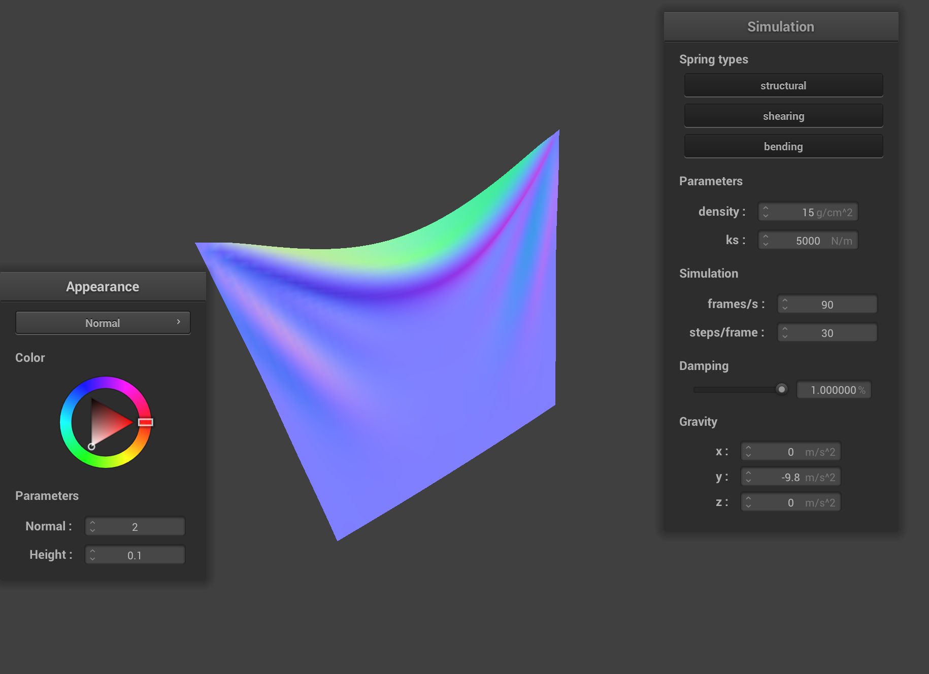
The high damping setting creates a much smoother-looking cloth, and reduces the speed at which the cloth falls down. It also causes it to come to rest almost immediately.
Cloth-Sphere Interaction
This section implements a sphere in space and has the cloth interact physically with this sphere. The technical challenge involved here was to enable the cloth to handle collisions with other objects in a physically accurate manner while preserving the ability to render in real-time.
Results: Cloth rests on sphere, with varying ks
As we increase the spring constant value, the cloth gets stiffer (see the writeup of Part 1 for more details).
The cloth cannot "bend to the shape" of the sphere (and also be as affected by the force of gravity) at higher ks settings, so the cloth doesn't “drape down” as much.

The cloth, resting on the sphere, with ks = 5000. Notice how the cloth is “draping down” a lot.

The cloth, resting on the sphere, with ks = 50000. Notice how the cloth is not “draping down” when ks is set so high.
Addendum: Cloth Rests on Plane
This section shows the cloth interacting with a plane in space.

Self-Collisions
This section demonstrates the phsyical simulation once the cloth was able to interact with itself. Notice that the cloth can now collide with itself.
The following screenshots show a falling cloth colliding with itself (in chronologically descending order):


Impact of Spring Constant and Density on Cloth Self-Collisions
Varying Spring Constant ks
Increasing ks, in effect, increases the "rigidty" of the cloth. Therefore, the cloth doesn't “want to fold in on itself” too much, which means that when the cloth tends to have fewer folds when it is lying on the plane.
This makes sense; a higher ks means a spring on the cloth would have to exert much more force to displace the other spring (and eventually create a fold in this scenario) than it has to with a low ks.
For the same reason, the impact of a self-collision is “smaller” (i.e. more visible) when ks is set to a higher value. This means that the cloth looks somewhat smoother when ks is set to a high value.
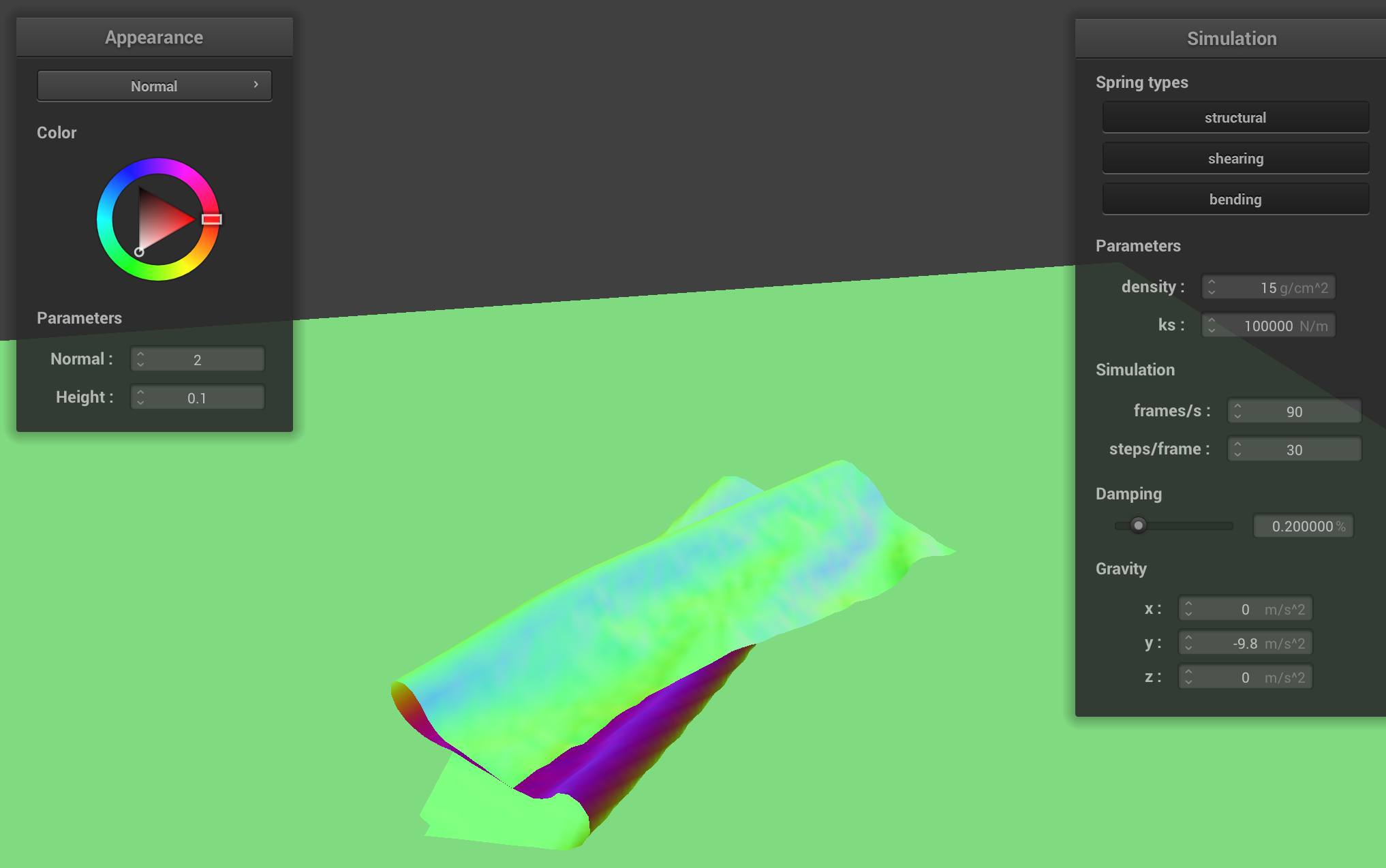
The cloth has far fewer folds when we set ks = 100000.
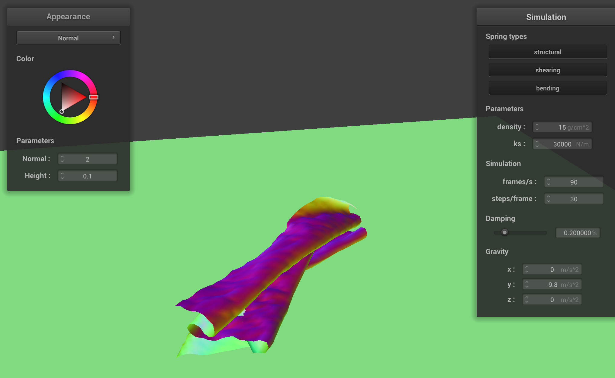
The cloth has more folds when ks = 30000. Furthermore, notice the cloth looks somewhat more "dimpled”.
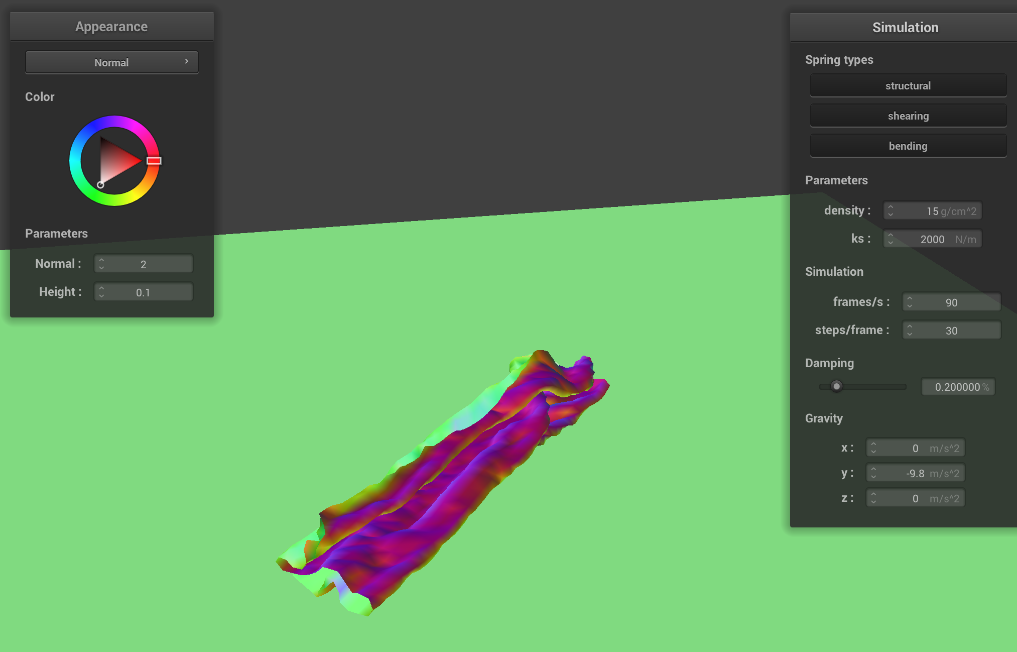
Even more folds (and “dimples”) are visible when ks is lowered further; this is consistent with the fact we are simulating a less rigid cloth.
Varying density
Increasing the density increases the mass of the cloth. As the mass of the cloth increases, the cloth tends to fold in on itself more, rather than flatly on the ground. Lower density cloths also tend to be smoother.
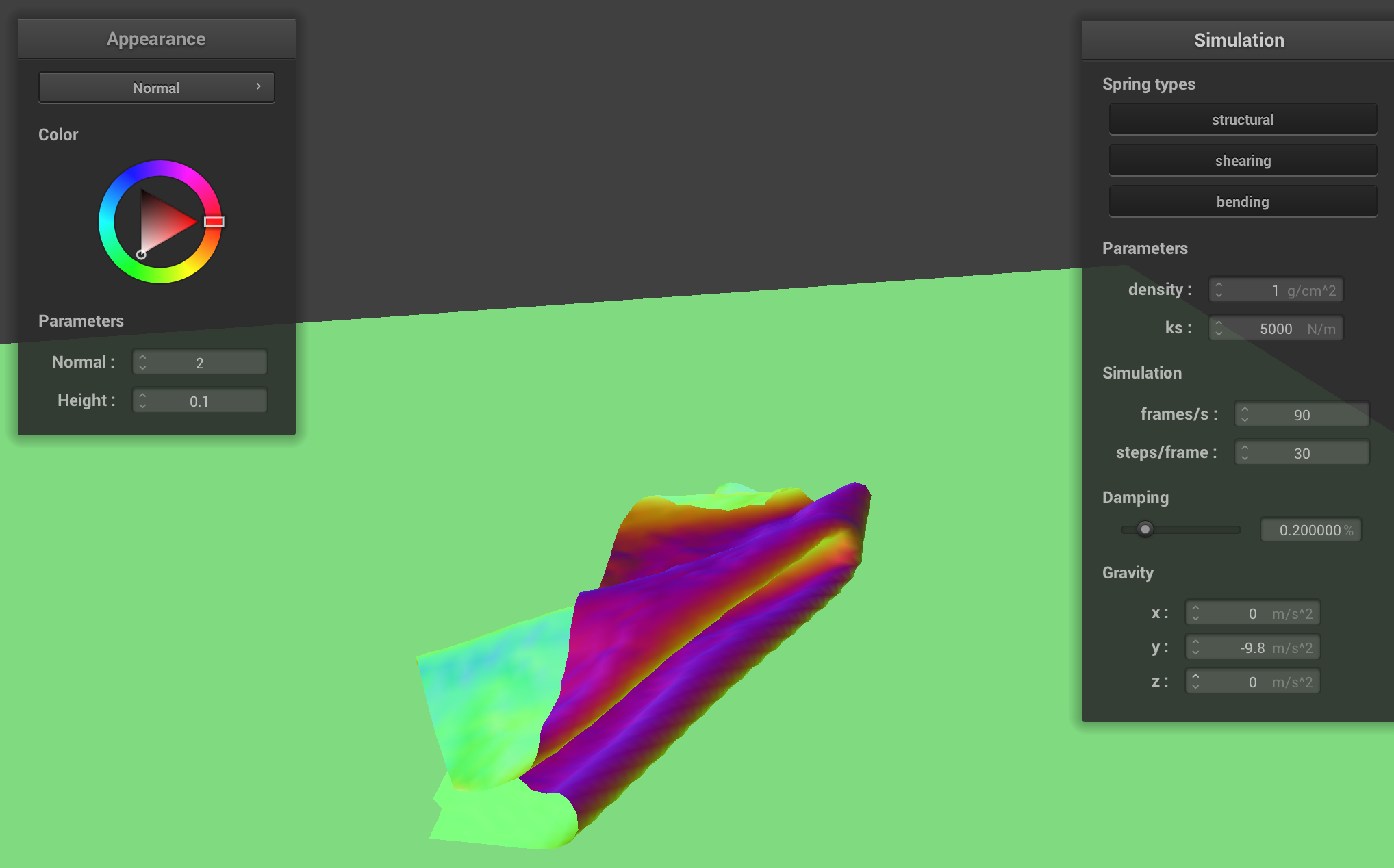
The cloth, generally resting on the plane, with density = 1.
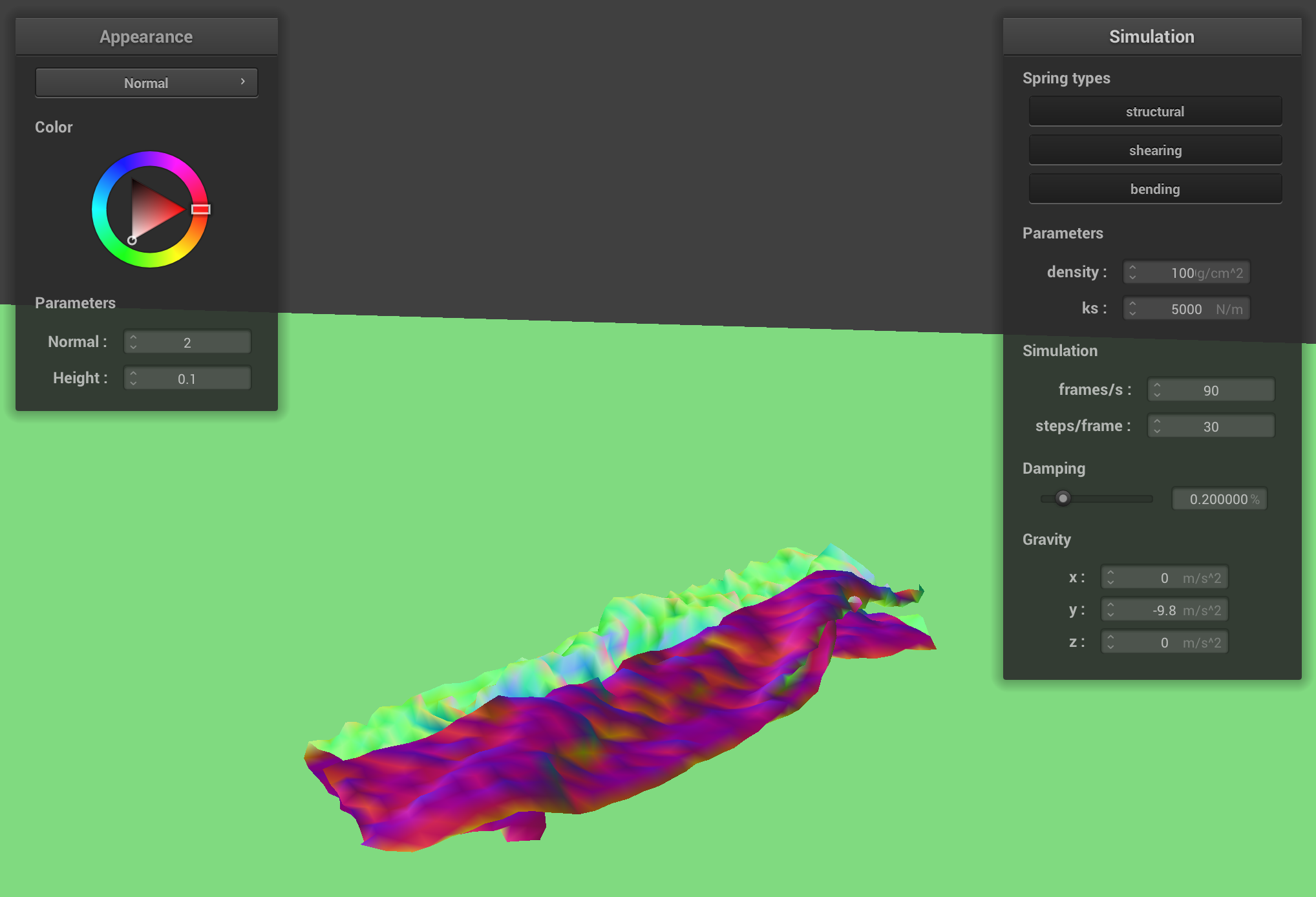
The cloth, generally resting on the plane, with density = 100.
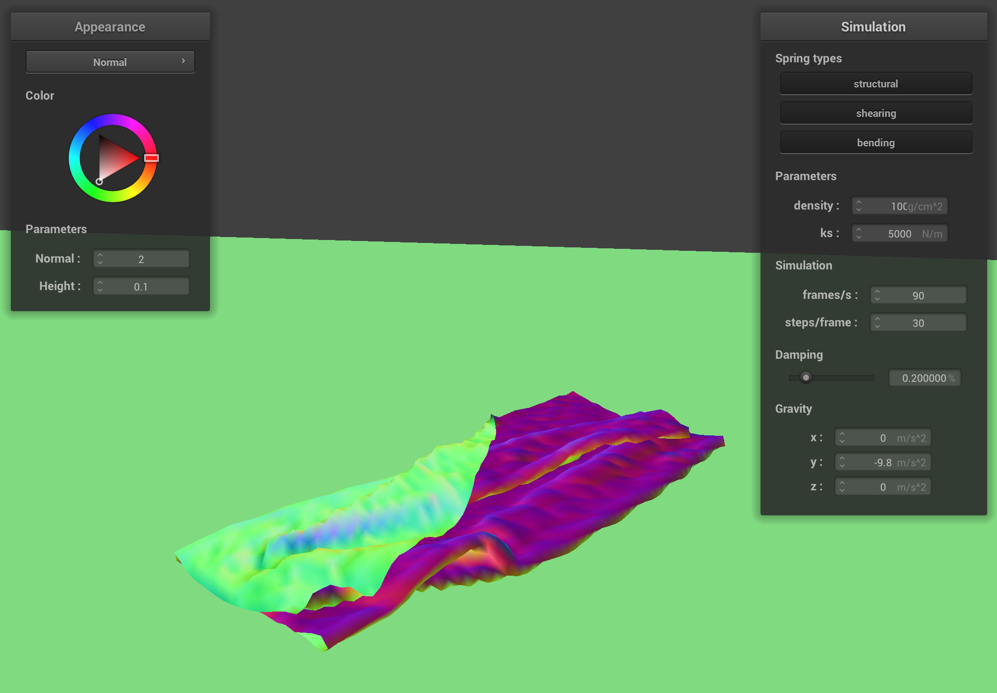
The cloth, generally resting on the plane, with density = 1000.
Shaders
Shaders are utilities that let us perform calculations in bulk as we render our scenes on the display. Our shaders calculate two things: the positions of vertices of our object (i.e. positions of vertices on the mesh) or the color of pixels (not exactly pixels—but rather the outputs of the objects created by the shader's calculations of vertex positions).
Since this data has to be calculated in bulk (for every vertex on the mesh/for every “sample" we take), but is not necessarily big (shaders only return a vector), a GPU is ideally optimized to carry out these calculations quickly and in a highly parallelized manner. Shaders, therefore (in our case), use the GPU to perform these calculations. This enables us to speed up our render times significantly.
Blinn-Phong Shading Model
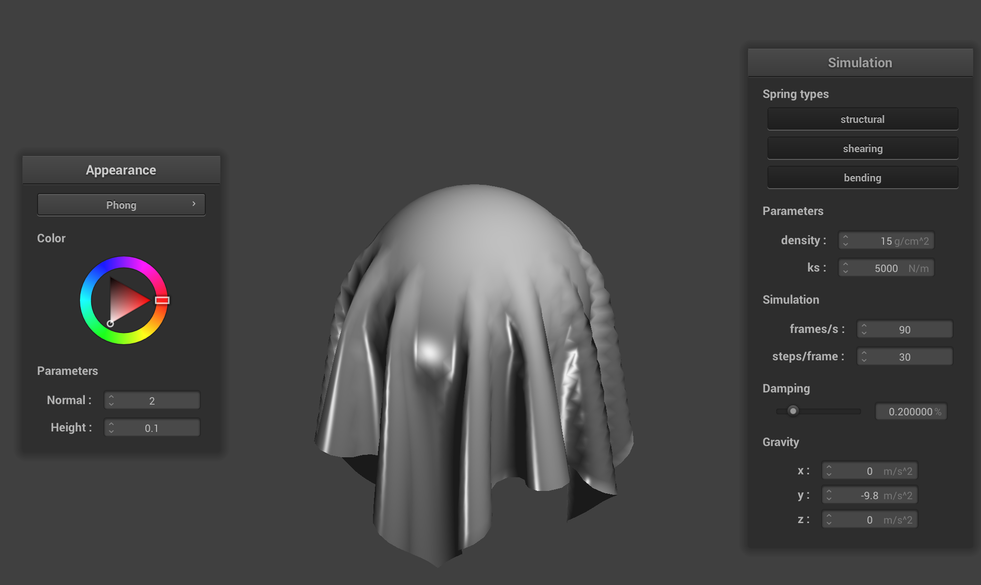
The Blinn-Phong shading model is a model that allows us to compute the appearance of a surface based on the light in the scene. While it is not a physically correct shading model, it nevertheless approximates (and accounts for) a lot of the visual effects of light that we see.
The alternative approach, raytracing, is a newer technology and much more computationally expensive, so the Blinn-Phong shading model is actually one of the “default” ways of shading things (calcualting the appearance of a surface) in computer graphics today.
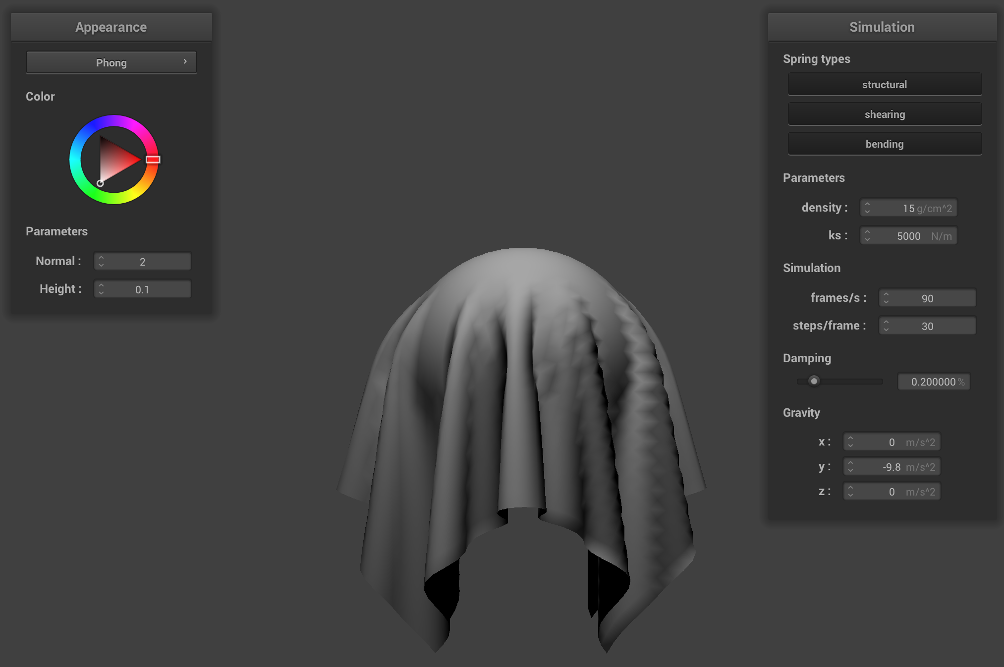
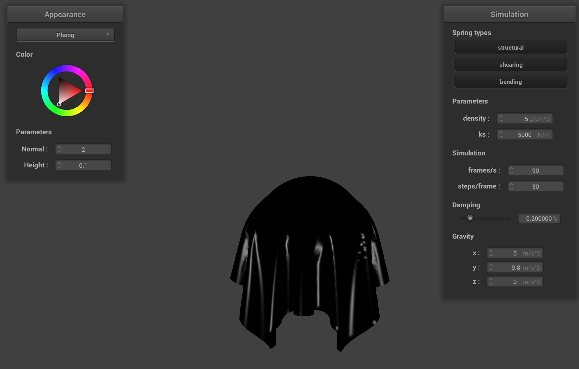
The model has three different components: ambient, diffuse, and specular. Each component is responsible for calculating a different visual effect, and these effects (components) are combined together to complete the model and thus compute a somewhat realistic appearance of a surface.
The ambient component is responsible for shading based on the “base” level of light (i.e. not on light sources). The diffuse component is based on light that comes from a light source but then is reflected out from the surface equally in all directions. The specular component is the most directionally-dependent, and responsible for the little bright spots (that move significantly based on the camera) from light sources you see on objects.
Ambient Only
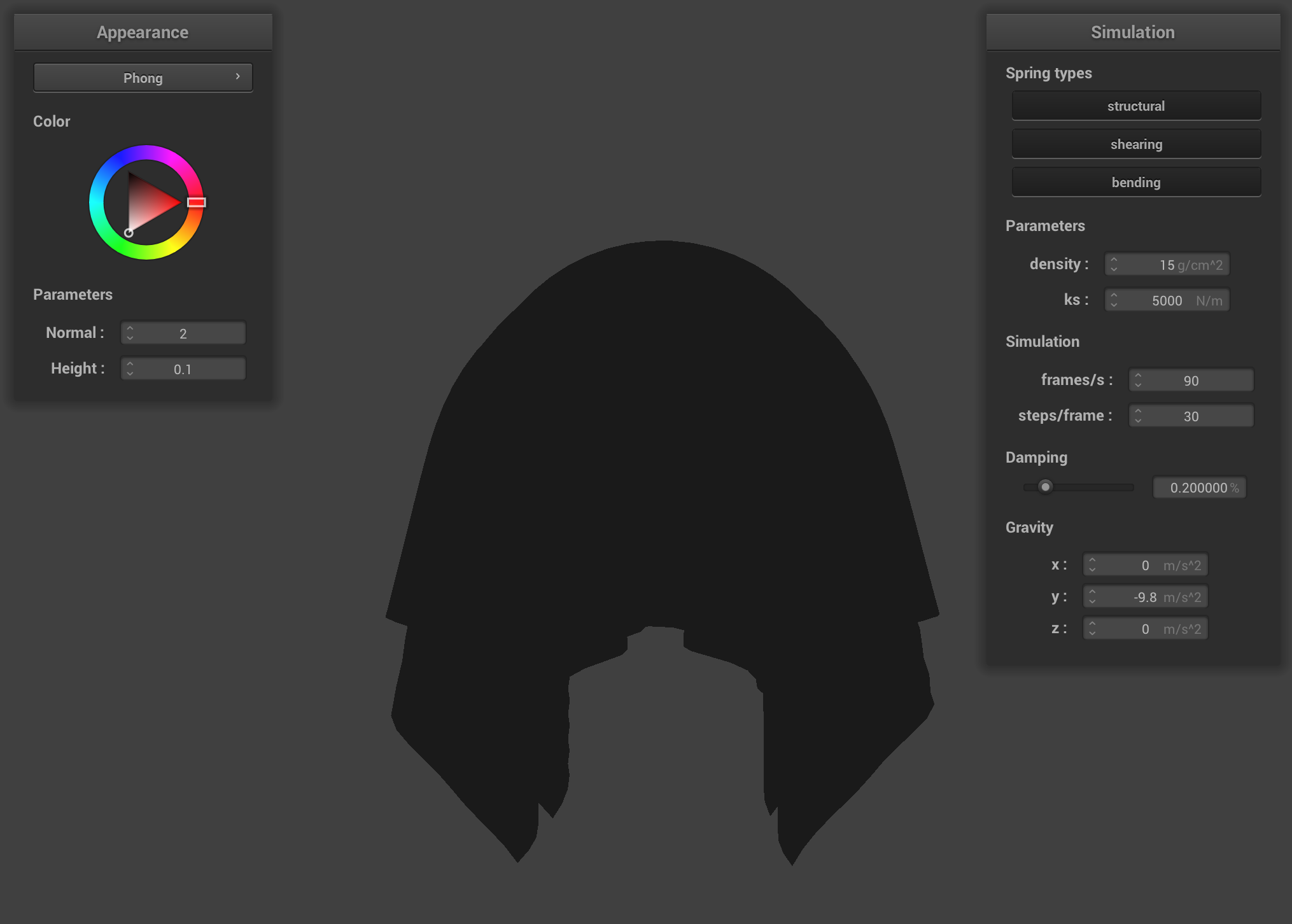
Diffuse Only
Specular Only
Entire Blinn-Phong Model
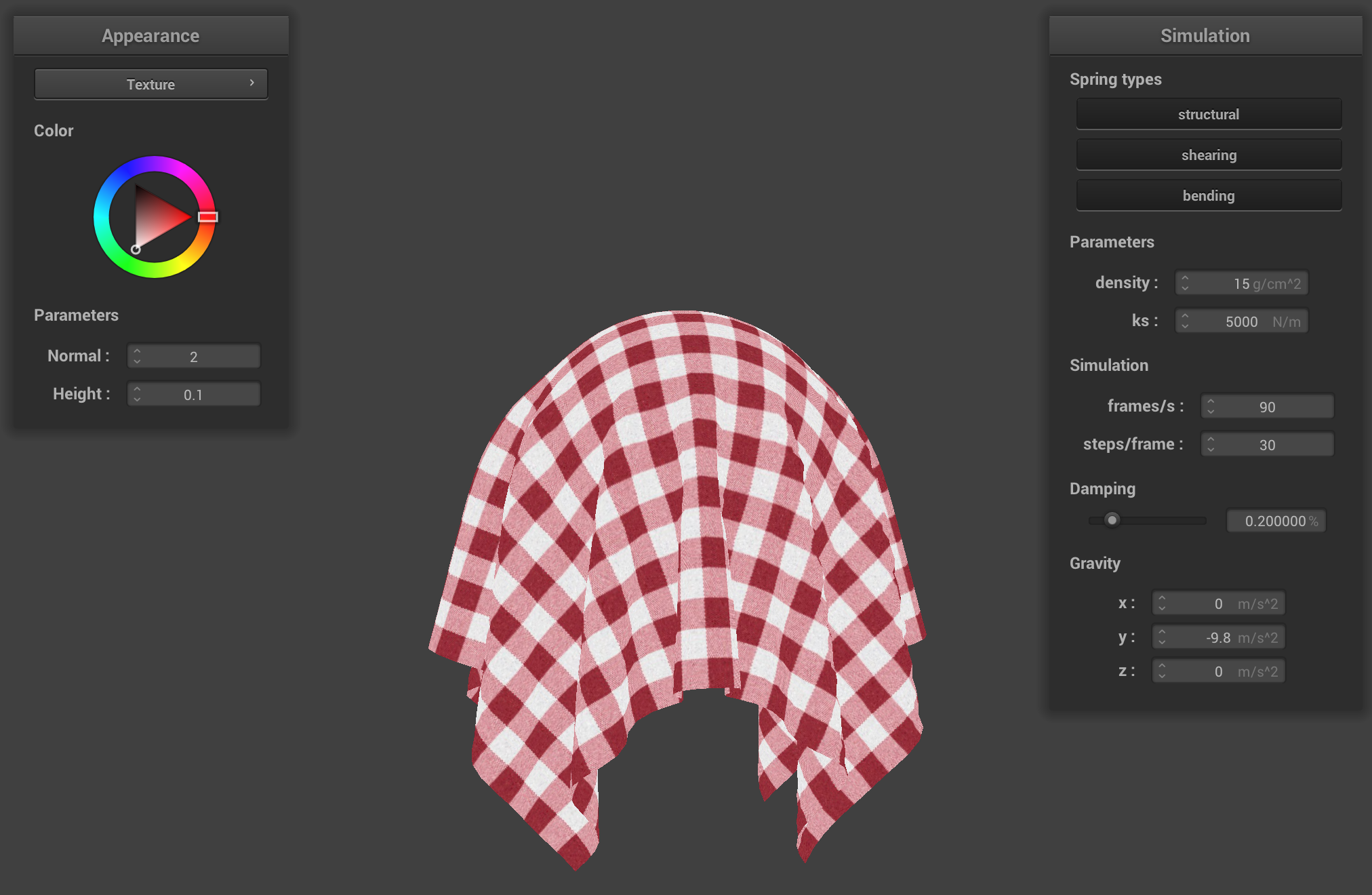
Texture Shader with Red-White Cloth Texture
Bump Mapping and Displacement Mapping
Bump Mapping vs Displacement Mapping
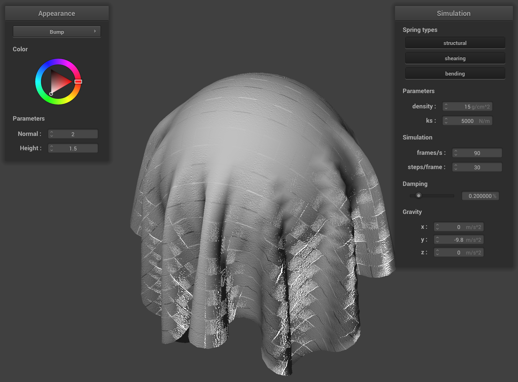
Bump Mapping.
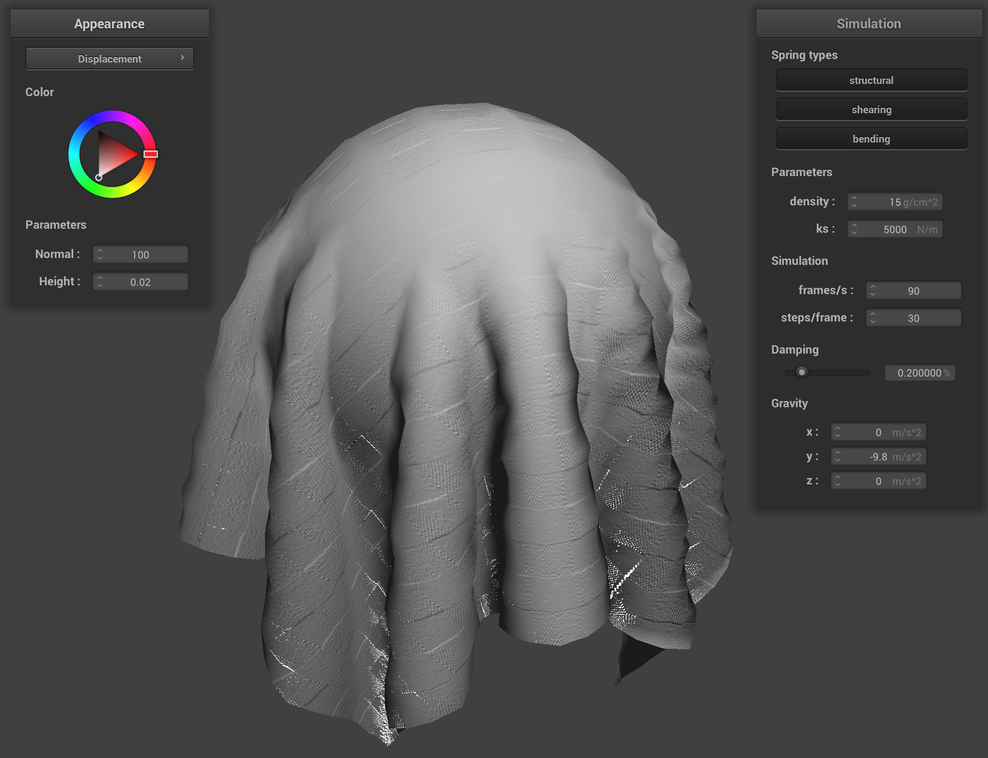
Displacement mapping.
With bump mapping, we only modify the normal vectors according to the height map—while with displacement vectors, we take this a step further and also modify the positions of the vertices themselves (i.e. actually change the geometry of the mesh). Displacement mapping is less "fake" compared to bump mapping, therefore.
This is clearly visible in the results. The cloth isn’t “draping down smoothly” with displacement mapping, but rather “fluctuating” based on the texture we used. The exact correspondence of heights/final vertex locations can change based on the height map we are using; a different height map (for a given texture) will mean the cloth will rest (physically) in a slightly different way. I chose to use the r component of the color vector stored at the texture coordinates for the vertex we were operating on, as suggested in the spec.
Coarse vs fine mapping
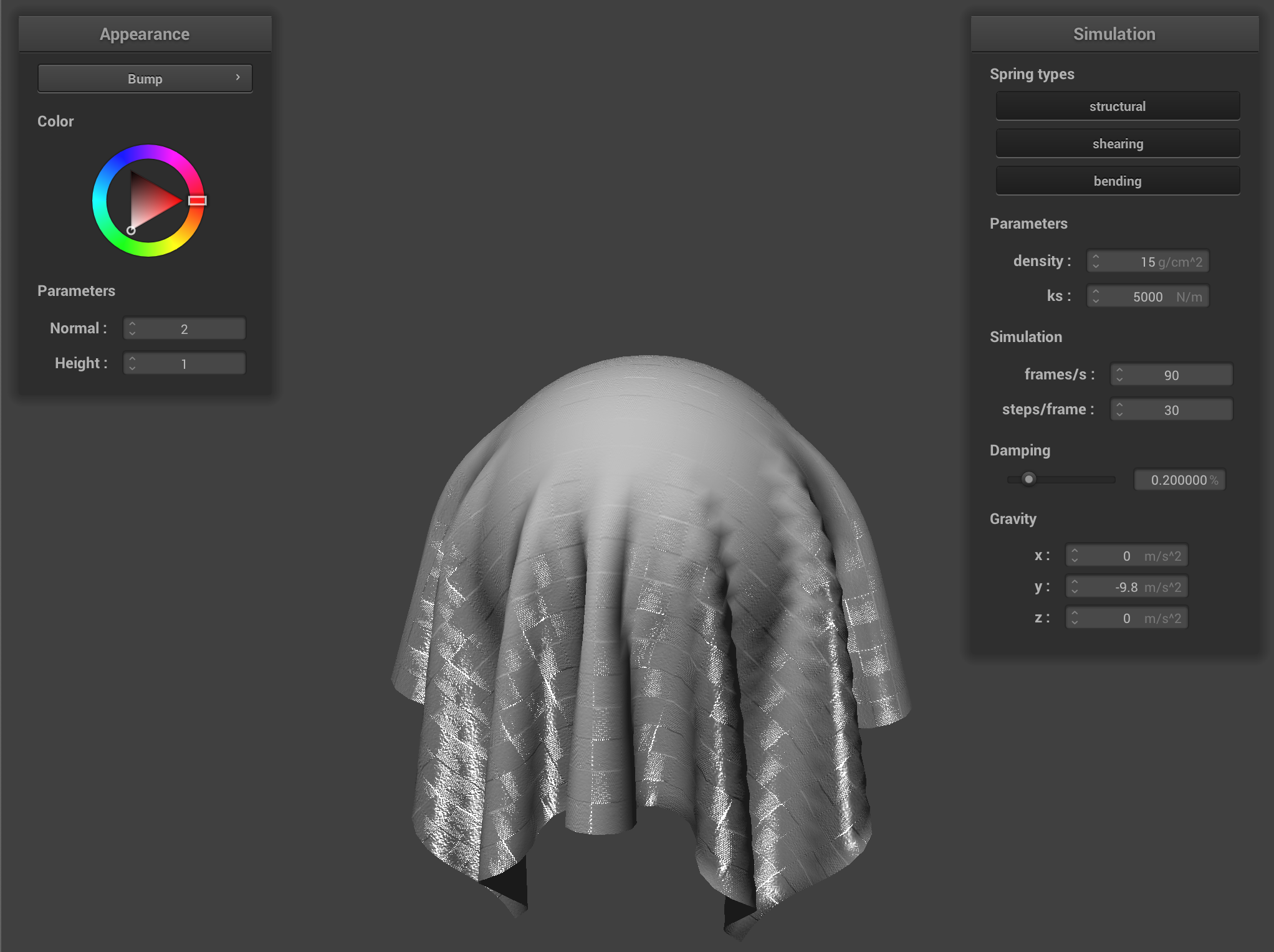
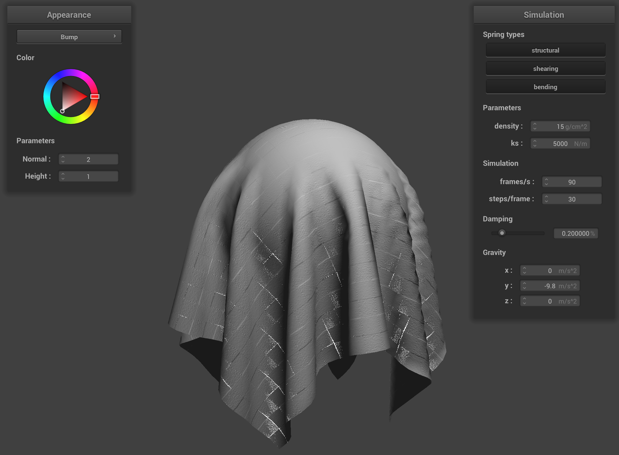
Bump mapping with coarse mesh (left), fine mesh (right)
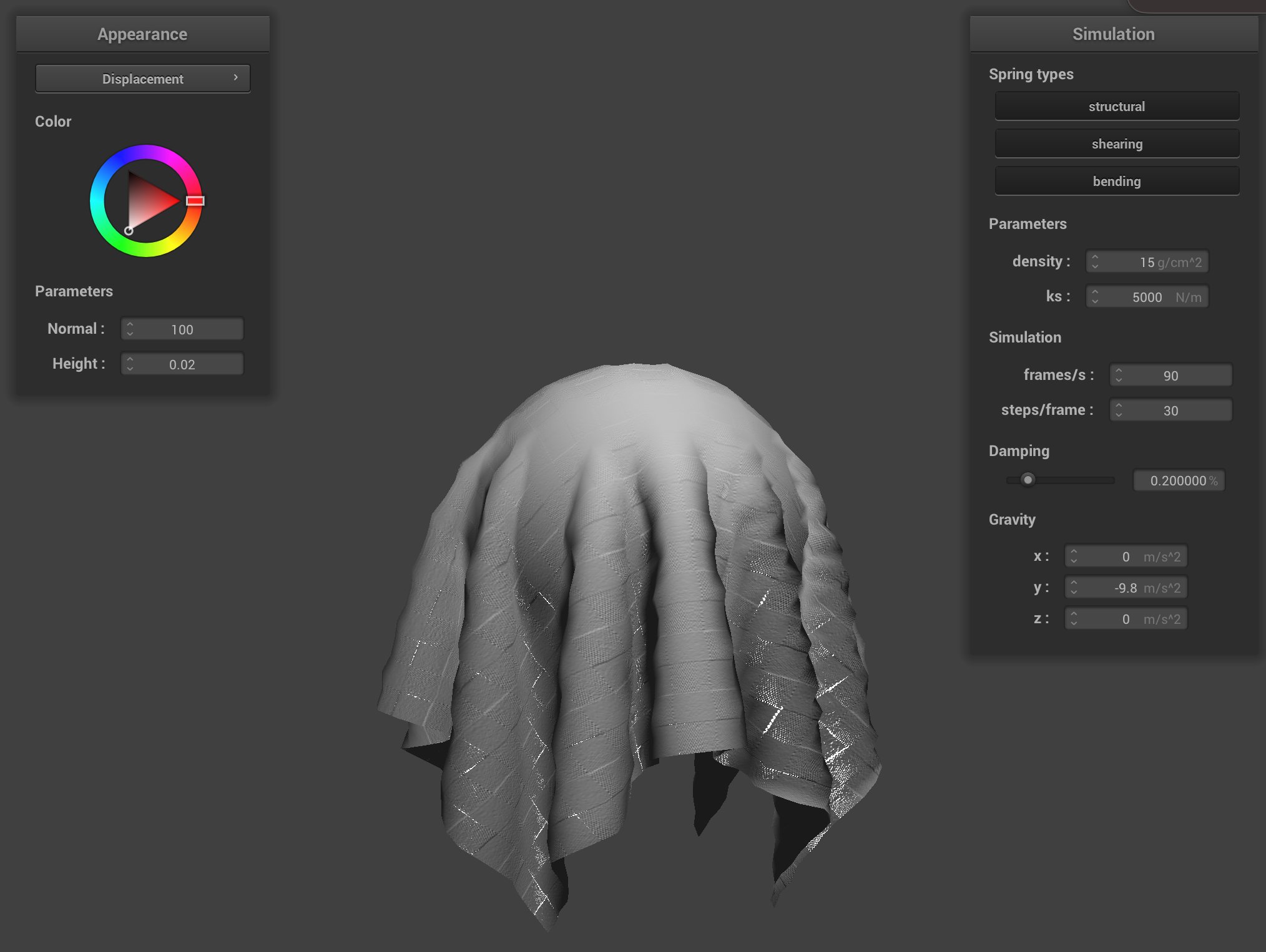

Displacement mapping with coarse mesh (left), fine mesh (right)
Displacement mapping is able to take advantage of the finer mesh, since it changes the position of the vertices according to the height map (as explained above, bump mapping does not do this—it just changes the position of the normals and hence the shading, but not the physical locations of the vertices in space). This enables us to see a difference between the coarse and fine mesh. The difference is not nearly as pronounced with bump mapping.
Mirror Shader
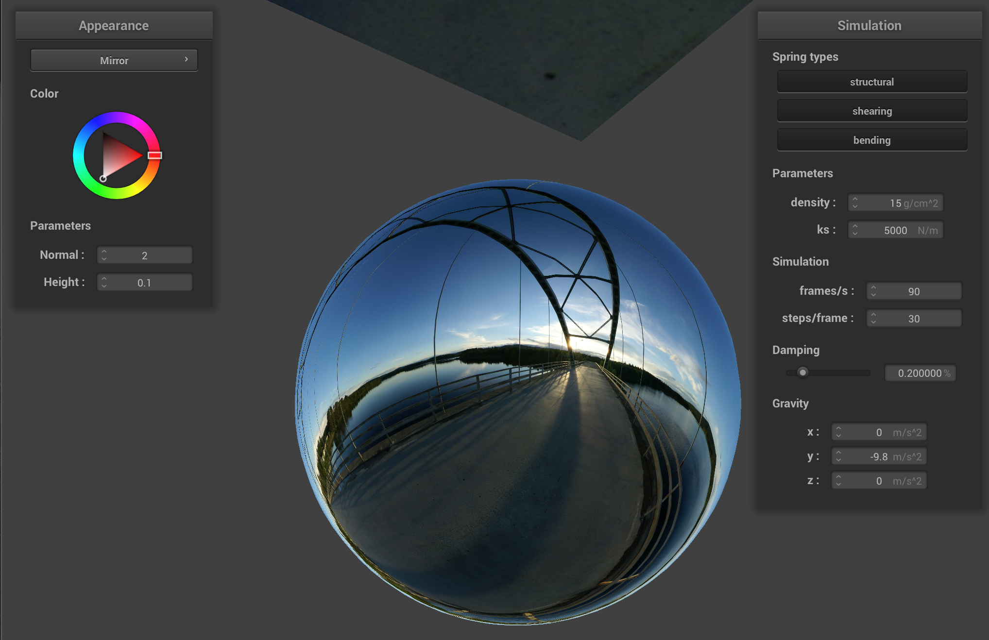
On Cloth and Sphere
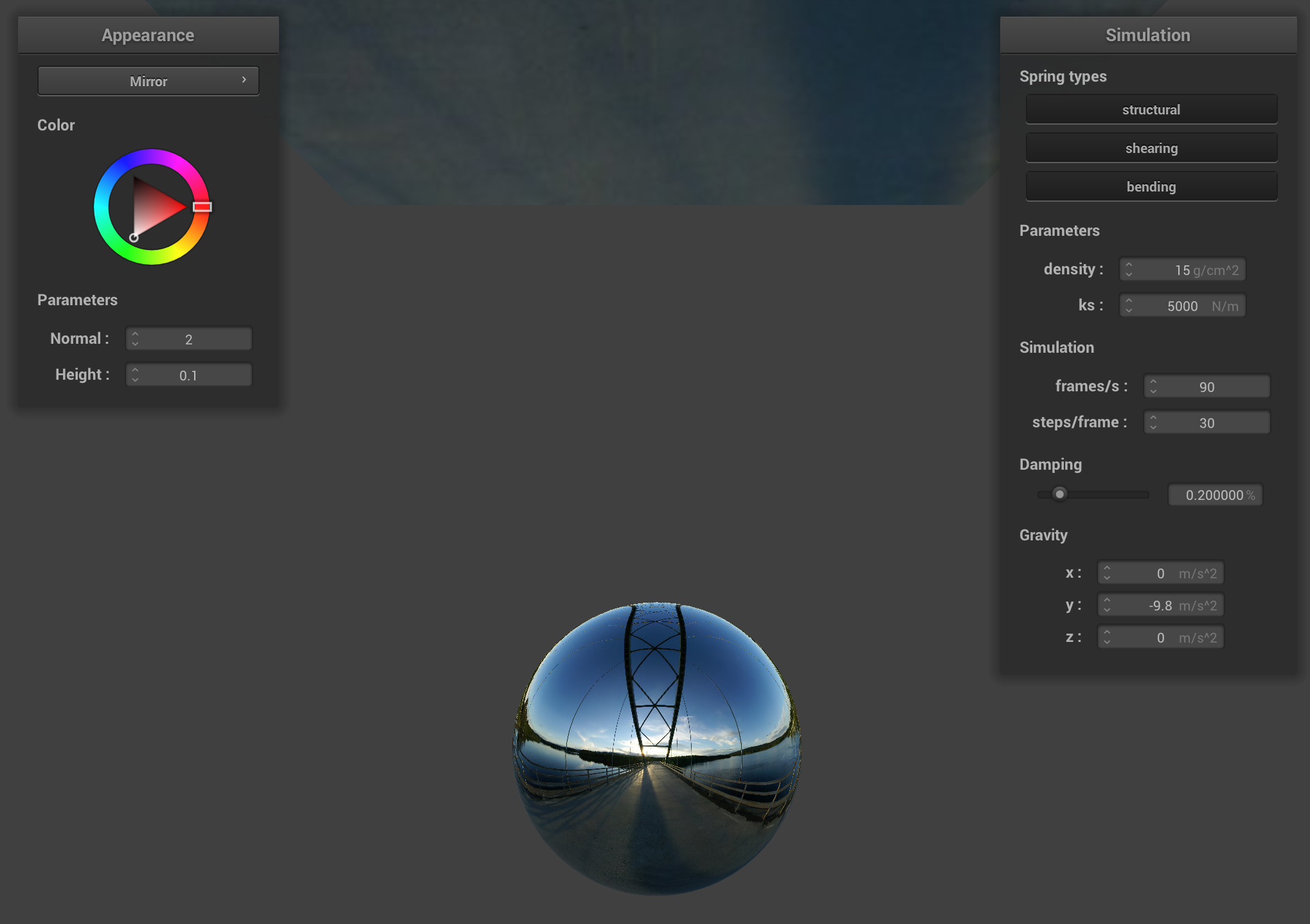
On Sphere
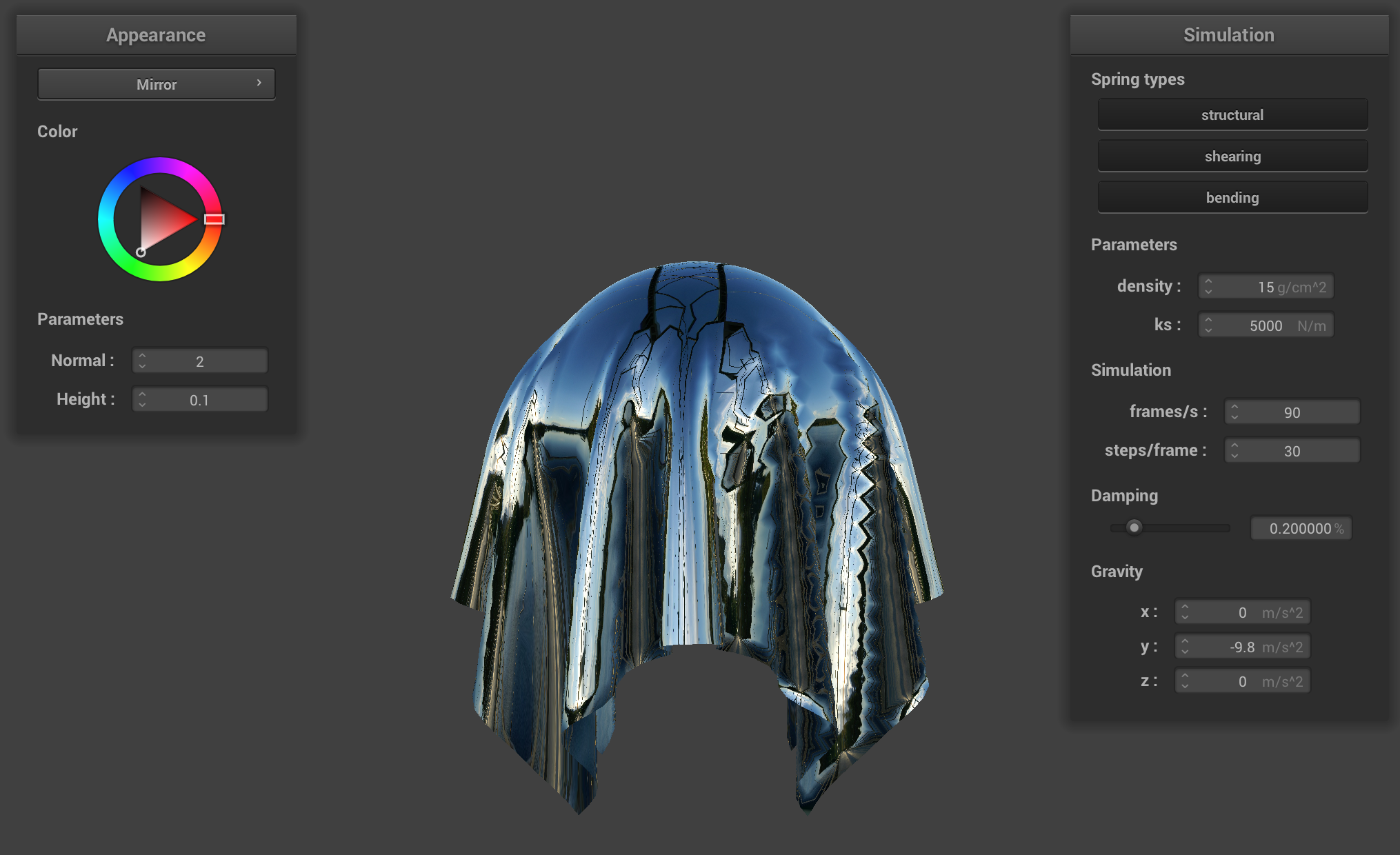
On Cloth
Bonus: Custom Shaders
I combined the Blinn-Phong model with texturing in order to have a nicely lit effect, in addition to simulating some transparency based on the lighting itself.
The result of combining Blinn-Phong with texturing made the renderings of texture cloths look a little bit more realistic, reminding me of a slight “beach towel” look.
For implementing transparency, I did some research and it turned out to be easy: reducing the alpha parameter would reduce the opacity. At first, I reduced this to 0.5 uniformly. The first two screenshots show this.
Finally, I then made this “shading-dependent", so that the larger stronger the diffuse component in the Blinn-Phong shading model, the more "solid" the object would look. Because this was done in a "proportional" manner, this meant that the areas with stronger specular shading would actually appear to be more transparent.
Custom shader screenshots
.png)
Notice the specular highlights from the light, indicating Blinn-Phong shading, on the textured cloth.
.png)
Notice the cloth is slightly transparent at the bottom.
Custom shader with per-vertex lighting-based transparency
.png)
Notice how parts that would typically have strong specular highlights are quite transparent; the other parts (which are mostly illuminated by diffuse lighting) are quite solid.